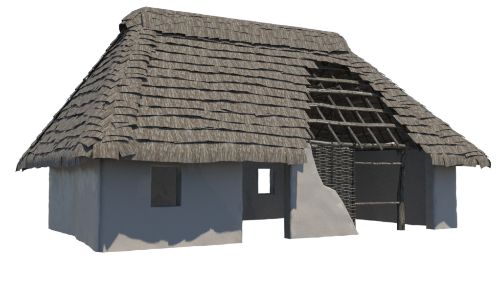
The final rendering of Structure 1 with a cutaway to show the internal framing of the building.
A Brief History of Charles Towne Landing and Structure 1
In 1670, Europeans colonists settled in what would become known as Charles Towne. Located on the opposite side of the Ashley River from modern-day Charleston, the site was located on Albemarle Point, which was bordered on one side by the Ashley and on the other by a marsh. The settlement consisted of small, linear lots that fronted a common, and also included a fortification. It is within this common that Structure 1, the subject of this reconstruction, would have stood.
Structure 1 has been the subject of a handful of archaeological investigations. An earlier investigation believed the building to be a hybrid of English frame construction and Barbadian vernacular architecture located within the fort. The most recent interpretation of the structure theorizes that the building could instead have been an English-influenced cratchet-style farm dependency located not in the fort, but in the commons.
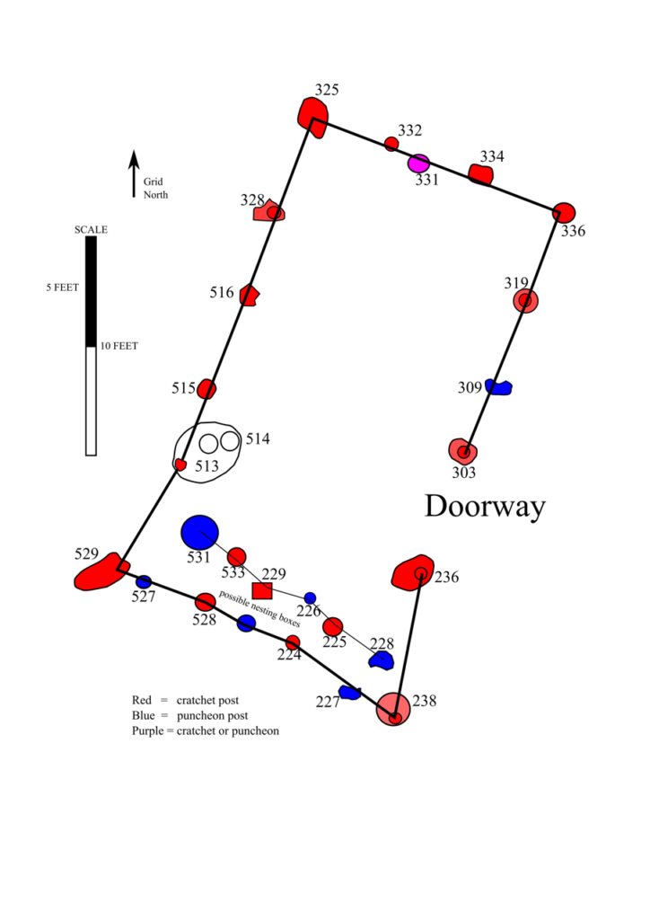
The archaeological plan of Structure 1, courtesy of Andrew Agha, PhD, RPA.
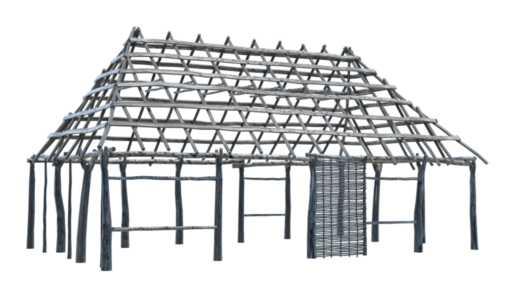
“Cratchets” are forked poles that would have been placed directly in the ground, with the plate lying within the forks. Puncheons are wedged between the ground and the plate, and then vines and thin pliable saplings or thick strips of wood are woven through the puncheons, which creates a surface upon which daub can be applied. The roof structure, consisting of rafters and collar ties arranged in a hipped shape, would have been assembled on the ground and lifted into place. The roof would likely be clad with a palmetto thatch, and the walls finished with daub, a mixture of clay, sand, straw, and water, which would have been thrown at the wall in order for it to key into the wattle (mat-like surface of woven wood).
A rendering showing how the cratchets, plates, and roof structure are assembled with a section of wattle between two of the cratchets.
Reconstructing Structure 1 in Autodesk 3ds Max
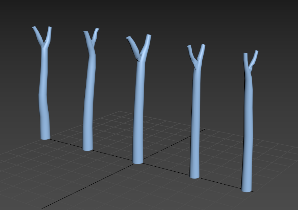
Early iterations of the cratchets.
The digital reconstruction of the cratchet-style building began with the construction of the cratchets in 3DS Max. The cratchets began as cylinder primitives. The first branch of the fork was shaped using bend and taper modifiers. The branch was then copied, rotated, and the vertices welded to the main body of the cratchet to create the two-pronged fork that characterized these types of post. The prongs were further joined using the bridge command. In order to give the cratchets more natural variation, the base shape was copied and then each copy was slightly reshaped by scaling and moving loop. Once five different cratchets had been made, they were instanced and moved into place in a spot which corresponded to position of the cratchets in the site plan of Structure 1 provided by Nicole Isenbarger and Andrew Agha.
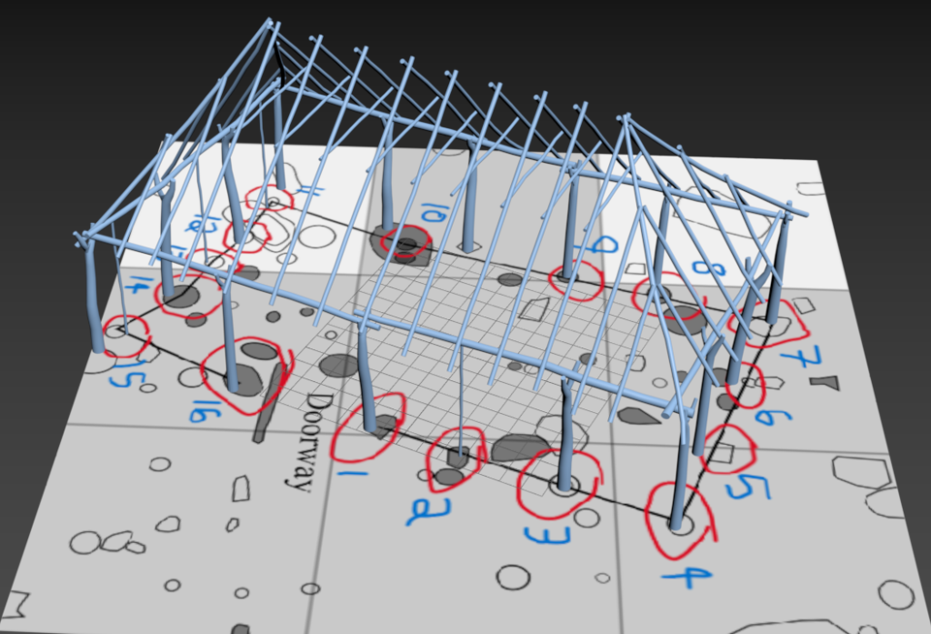
The plate, rafters, and collar ties assembled atop the archaeological plan of Structure 1.
Once the cratchets were in place, the plate was created using cylinder primitives that were shaped and resized like the cratchets in order to give them natural variation. Once the plate was in place, pairs of rafters were made with cylinder primitives that were reshaped like the cratchets and plates. Once the rafters were in place, purlins were added using box primitives that were reshaped to make them more naturally shaped, provided a surface for the thatch to be fixed to. At this time, puncheons were also added based on their placement in the site plan, and horizontal window sills and headers were placed to demarcate the location of the windows.
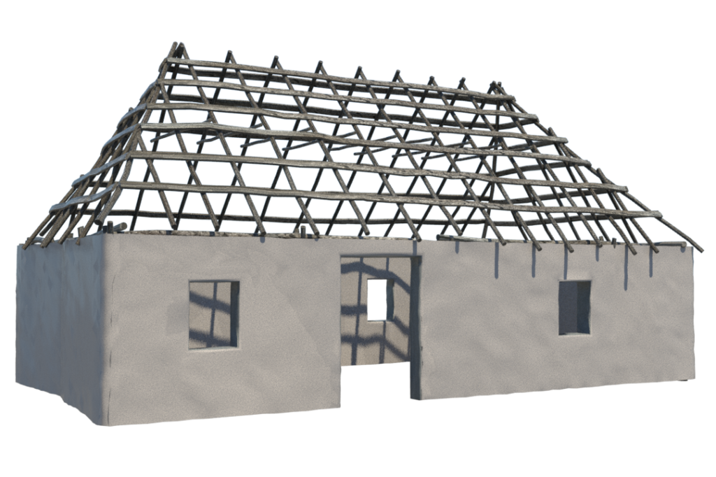
The frame of Structure 1 with daubed walls.
To finish the building, a line was drawn around the cratchets and extruded up to make the solid wall surface. Loops and control points were moved and scaled to make the shape better reflect the layout of the cratchets. Once the basic mass of the wall was laid out, a boolean operator was used to cut box primitives from the main mass of the wall, creating windows. The edges of all of the windows and the corners of the building were rounded slightly using the chamfer tool in order to give them the more natural shape of daubed walls. Once the shape was set, more edge loops were added with the swift loop tool, and then the noise modifier was applied to give the wall surface a rougher texture to simulate daub.
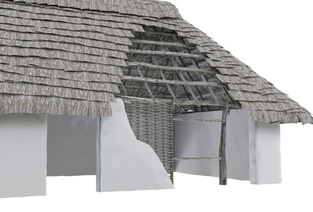
A closeup of the final cutaway model.
The last surface to be finished was the roof. The hipped roof shape was created using the box primitive, and then welding vertices together to get the hipped shape. In order to add thatch to the roof, a picture of a dried palmetto frond was imported into Adobe Substance Sampler to create a thatch material that could be used in 3DS Max. This material was applied to tiles which had been edited with the noise modifier to give them a surface that would be more varied like thatch. These tiles were then painted onto the main roof structure, and then cleaned with the slice plane tool. Caps were made for the joints at the corners of the hipped roof by bending the tiles so that they would cover the seams between the different faces of the roof.
Final Models
Two final models were produced for Charles Towne Landing State Historic Site. One represents how the building may have looked in the 1670s, and the other features a cutaway to showcase the internal framing of the structure. Both of these models can be found below.
It is important to remember that these models represent what may have been at the site of Structure 1 to the best of my ability, using archaeological reports, secondary sources, and examples reconstructed by other historic sites. It is impossible to guarantee exactly what would have been at the site, but this is the current best approximation of what would have been at the site.